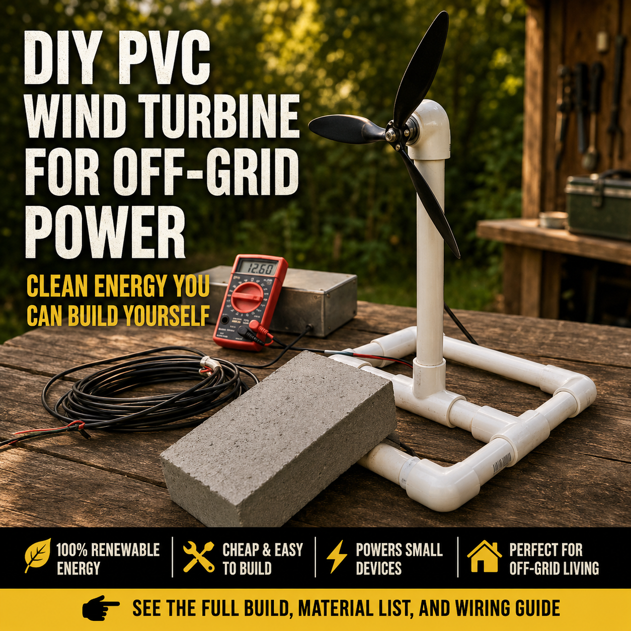
A small wind turbine can turn an ordinary breeze into a measurable amount of electricity.
The basic process is straightforward:
- Wind pushes the propeller.
- The propeller spins the shaft of a small DC motor.
- The rotating motor produces electrical voltage.
- Wires carry that electricity to a meter or appropriately matched low-power load.
The project does not require gasoline, sunlight, or a wall outlet while operating. It can demonstrate renewable-energy principles, illuminate a small LED under favorable conditions, or help you compare wind conditions around your property.
However, this compact PVC model should not be confused with a residential wind-energy system.
A genuine home wind system normally includes an aerodynamically designed rotor, matched generator, tail or yaw controls, engineered tower, wiring, controller, batteries or inverter, grounding, protective equipment, and sometimes utility-interconnection hardware. (The Department of Energy’s Energy.gov)
This PVC version is most useful as:
- A renewable-energy demonstration
- A supervised family science project
- A low-voltage electronics experiment
- A wind-site comparison tool
- A temporary LED-lighting experiment
- A foundation for learning about generators and charging systems
It should not be connected directly to household wiring, utility power, a phone, lithium batteries, or a standard inverter.
What This Project Actually Builds
The completed device is a small horizontal-axis wind turbine.
Its propeller rotates around a horizontal shaft. A tail vane keeps the rotor facing approximately into the wind, while a swivel beneath the generator allows the upper assembly to turn as the wind changes direction.
The Department of Energy identifies horizontal-axis turbines as the most common wind-turbine arrangement. The rotor’s diameter determines its swept area—the amount of moving air available to the turbine—and the tail helps keep a small turbine facing into the wind. (The Department of Energy’s Energy.gov)
The original tutorial incorrectly suggests that vertical-axis turbines are generally more efficient than horizontal-axis models. There is no universal rule that one orientation is always more efficient. Performance depends on the rotor design, generator, wind conditions, operating speed, site turbulence, and intended application.
This particular project is not a vertical-axis turbine.
Four Important Corrections to the Viral Design
1. A hobby motor is not a rated wind generator
A small brushed DC motor can produce electricity when its shaft is turned, but the voltage and current printed on its label usually describe how it operates as a motor.
For example, a label reading “3 volts, 350 milliamps” does not promise that it will generate 3 volts at 350 milliamps in a backyard breeze.
Generator output depends on:
- Rotational speed
- Motor construction
- Propeller size and pitch
- Bearing friction
- Electrical load
- Wind speed
- Mechanical losses
Measure the actual output rather than assuming the motor’s printed rating is a generation rating.
2. Do not use duct tape as the primary motor mount
Tape can loosen in sunlight, heat, rain, vibration, and changing temperatures.
Secure the motor with:
- A fitted metal bracket
- A padded pipe clamp
- A U-bolt
- A properly sized motor clamp
- Bolts and locking nuts
Tape may be used temporarily to protect or cushion a component, but it should not be the only thing preventing a spinning propeller from separating from the stand.
3. Do not cut the propeller from a brittle bucket lid
An unbalanced homemade blade can vibrate, strike the frame, or break apart at speed.
Use a factory-made plastic propeller that:
- Fits the motor shaft
- Has no cracks
- Is balanced
- Is designed for rotational use
- Has rounded edges
- Is small enough for the stand
Never operate a damaged or visibly wobbling propeller.
4. Do not connect the motor directly to a battery
Wind voltage changes constantly.
A battery requires controlled charging appropriate to its chemistry, voltage, temperature, and condition. NREL describes wind-battery systems as including a wind charge controller that regulates battery current and prevents damaging overcharge; some systems must redirect excess energy to a dump load. (NREL Docs)
This beginner turbine should first be connected only to:
- A digital multimeter
- A suitable low-voltage LED test circuit
- A small resistor load
- A capacitor-based demonstration circuit
How Wind Speed Affects the Result
Wind energy changes dramatically with wind speed.
The available wind power is commonly represented as:
Power = ½ × air density × swept area × wind speed³ × power coefficient
Because wind speed is cubed, a moderate increase in wind speed can produce a much larger increase in the energy available to the rotor. The turbine captures only part of that available energy, and further losses occur in the bearings, motor, wiring, rectifier, and load. (The Department of Energy’s Energy.gov)
This explains why the turbine might:
- Do nothing in a light breeze
- Produce measurable voltage in moderate wind
- Suddenly produce a much higher voltage during a gust
It also explains why electrical protection and mechanical control matter even on a small project.
Materials
The dimensions below create a portable, ground-level demonstration turbine. Adjust them to match your propeller and motor.
PVC base and post
- Approximately 8 feet of ¾-inch or 1-inch Schedule 40 PVC pipe
- Three PVC tee fittings
- Four PVC end caps
- One upright post approximately 18 to 24 inches long
- PVC primer and cement
- Two sandbags or removable base weights
The PVC stand is not an engineered tower. Keep it low enough to inspect and retrieve without climbing.
Swivel head
- Small turntable or lazy-Susan bearing
- Two pieces of exterior plywood
- Bolts, washers, and locking nuts
- Two mechanical rotation stops
- Optional weather cover
A purpose-built small yaw bearing may be used instead.
Do not leave the upper assembly free to rotate indefinitely unless the electrical system includes an appropriately rated slip ring. Otherwise, repeated rotation will twist and damage the wires.
Generator and rotor
- Small brushed DC motor
- Factory-made lightweight plastic propeller
- Shaft adapter matched to the motor
- Motor mounting clamp or bracket
- Locking hardware
- Protective hub cover, optional
Choose a propeller that is compatible with the motor’s shaft and intended rotational direction.
Tail assembly
- Corrugated plastic sheet or thin exterior plywood
- Narrow aluminum or wooden tail arm
- Bolts and locking nuts
- Lightweight angle brackets
A tail vane around 8 by 12 inches is usually adequate for a small demonstration unit, although the ideal size depends on the rotor and generator assembly.
Electrical materials
- Flexible two-conductor stranded wire
- Rubber grommets
- Strain-relief clamp
- Heat-shrink tubing
- Solder and soldering iron
- Digital multimeter
- Schottky blocking diode
- Appropriate current-limiting resistor
- Low-voltage LED module
- Small inline fuse or resettable protector matched to the circuit
- Weather-resistant electrical box, optional
Do not use a damaged household extension cord merely because it is available. Use clean, correctly sized low-voltage wire with intact insulation.
Tools
- Tape measure
- Marker
- PVC cutter or fine-tooth saw
- Drill
- Drill bits
- Screwdrivers
- Adjustable wrench
- Wire stripper
- Soldering equipment
- Small file
- Safety glasses
- Work gloves
- Clamps
Step 1: Test the Motor Before Building
Connect the motor leads to a digital multimeter set to measure DC voltage.
Turn the motor shaft by hand.
The meter should display a small voltage. Reversing the direction of rotation should reverse the polarity shown on the meter.
Next, temporarily install the propeller and turn it carefully by hand.
Confirm that:
- The shaft rotates freely
- The propeller does not wobble
- The hub grips the shaft properly
- The motor bearings do not grind
- The motor produces measurable voltage
A motor that requires substantial force to turn may not perform well in a small wind turbine.
Do not spin the propeller with compressed air. It can exceed a safe rotational speed almost instantly.
Step 2: Build a Broad H-Shaped Base
A broad base is safer than the narrow three-legged stand often shown in small DIY projects.
Create two parallel PVC rails approximately 24 inches long. Each rail can be made from two 12-inch sections joined by a tee fitting at its center.
Connect the two rail tees with an 18-inch crossbar. Add the third tee at the center of this crossbar with its open branch facing upward.
Insert the vertical post into that center tee.
Install end caps on the four exposed rail ends.
The completed base should resemble a wide letter H, with the upright post rising from the middle.
Before gluing:
- Assemble everything dry.
- Place the unit on a level surface.
- Check that the upright is vertical.
- Confirm that the propeller will clear the ground and base.
- Mark the orientation of every fitting.
Disassemble and cement one connection at a time according to the PVC cement manufacturer’s instructions.
Allow it to cure fully before installing the generator.
Step 3: Weight the Base
A lightweight PVC frame can tip in wind.
Place one sandbag across each side rail or secure the base to a broad plywood platform. The weight must not press against or deform the vertical post.
Never stabilize the turbine by holding it while the propeller is turning.
For outdoor testing, the base should remain stable when pushed gently from every direction.
When it rocks, twists, or lifts from the ground, stop and widen or weight it before proceeding.
Step 4: Build the Swivel Platform
Cut two small plywood squares approximately six inches wide.
Attach one square securely to the top of the PVC upright using a suitable pipe clamp or flange arrangement.
Install the turntable bearing between the two plywood pieces.
The lower plate remains stationary while the upper plate rotates.
Attach two mechanical stops so the upper plate can turn toward changing wind but cannot complete unlimited rotations. Approximately 180 to 270 degrees of total movement is sufficient for a temporary demonstration site.
The stops protect the wiring from becoming repeatedly twisted.
Turn the empty platform by hand and confirm that it moves smoothly without excessive looseness.
A plumbing union may appear to provide a convenient swivel, but plumbing unions are not designed as outdoor rotational bearings. A proper bearing or swivel bracket provides more predictable movement.
Step 5: Mount the Motor
Install a rigid bracket on the upper swivel plate.
Place the motor horizontally with its shaft extending beyond the front of the platform.
Secure it using:
- A padded metal clamp
- A motor-specific bracket
- A U-bolt with a rubber cushion
- Locking nuts
Do not overtighten the clamp around a thin motor housing.
The motor shaft must remain parallel to the upper platform. Misalignment can cause the propeller to wobble or strike the stand.
Pull gently on the motor after mounting it. It should not rotate, slide, or lift from the bracket.
Step 6: Install the Tail Arm and Vane
Attach a lightweight tail arm behind the motor.
The tail arm must extend far enough behind the swivel point to provide leverage without making the entire upper assembly unstable.
Cut the tail vane from corrugated plastic or thin plywood.
Round every corner.
Bolt the vane vertically to the tail arm. Use washers so the bolt heads cannot pull through thin plastic.
Viewed from above, the motor shaft, swivel center, and tail arm should form one straight line.
When wind strikes the tail from the side, the upper assembly should turn until the propeller faces into the wind.
Do not use a large, heavy tail. Excess weight increases stress on the swivel and PVC post.
Step 7: Route the Wires
Solder flexible wires to the motor terminals.
Cover the joints with heat-shrink tubing.
Create a small drip loop so rainwater cannot follow the wires directly into the motor.
Route the wires down the outside of the swivel assembly, through a rubber-grommeted opening, and along the PVC post.
Leave a flexible service loop near the swivel. It should be long enough for the permitted yaw movement but short enough that it cannot enter the propeller.
Secure the wire at several points with strain-relief clips.
Do not pull the full cable weight from the motor’s solder terminals.
At the base, terminate the wires inside a small electrical box or connect them directly to the test meter.
Step 8: Install the Propeller
Disconnect the wires from every load.
Fit the propeller hub onto the motor shaft.
Use the manufacturer’s shaft adapter, collet, or retaining hardware. Do not rely on glue alone.
Rotate the propeller slowly by hand.
Check its clearance from:
- The PVC post
- Motor bracket
- Wiring
- Tail arm
- Base
- Ground
Viewed from the front, the propeller should remain in a consistent plane.
Stop and correct the assembly when the hub appears off-center or any blade passes closer to the frame than the others.
Never stand directly in the plane of the rotor during testing.
Step 9: Conduct an Indoor Electrical Test
Keep the turbine firmly clamped or weighted.
Aim a household fan toward the propeller from a safe distance. Use the fan’s lowest setting first.
Do not place the fan or turbine where either can fall.
Connect only the multimeter.
Record:
- Wind source
- Approximate distance
- Meter voltage
- Rotation direction
- Visible vibration
- Noise
- Stability
Increase the fan setting gradually.
A voltage reading with no electrical load is called open-circuit voltage. It does not tell you how much useful power the generator can deliver.
To estimate usable power, the turbine must be tested with a known load while measuring both voltage and current.
Step 10: Add a Small LED Load
After measuring the maximum test voltage, select a low-voltage LED module that is appropriate for that range.
A basic circuit may include:
- Generator
- Schottky blocking diode
- Current-limiting resistor or regulated LED module
- LED
- Optional smoothing capacitor
The blocking diode reduces reverse current and protects against polarity changes when the rotor moves backward.
The resistor or regulator prevents excessive LED current during gusts.
Do not connect a bare LED directly unless its current is properly limited. LEDs can fail even when the voltage seems low.
When unsure about resistor selection or circuit polarity, ask someone experienced with low-voltage electronics to inspect the circuit before operating it.
Step 11: Perform a Supervised Outdoor Test
Choose a clear day with mild, steady wind.
Place the turbine:
- On level ground
- Far from roads and walkways
- Away from children and pets
- Away from windows
- Away from vehicles
- Away from trees and loose objects
- Well clear of overhead power lines
OSHA identifies energized overhead lines as a severe electrocution hazard and uses at least 10 feet as a minimum worker-clearance baseline in relevant wind-energy operations. Do not erect or carry this project near power lines under any circumstances. (OSHA)
Weight or anchor the base.
Stand behind and to the side of the rotor—not in front of it or directly beside its rotation plane.
Observe whether the tail turns the propeller into the wind.
Stop the test when:
- The base moves
- The post bends
- The propeller wobbles
- The motor mount loosens
- The wire twists tightly
- The turbine vibrates heavily
- The wind becomes gusty
- A storm approaches
Lower and store the turbine when it is not under direct supervision.
What Can It Realistically Power?
This project has a very small rotor and generator.
Under favorable conditions, it may be able to:
- Produce a measurable voltage
- Light a small LED
- Charge a capacitor slowly
- Power a tiny sensor intermittently
- Demonstrate changes in wind speed
- Test simple voltage-regulation circuits
It should not be advertised as capable of reliably:
- Charging a phone
- Charging a 12-volt car battery
- Operating a radio
- Running household lights
- Powering an appliance
- Operating a refrigerator
- Feeding a conventional inverter
- Reducing a household electric bill
The original design uses a small 3-volt hobby motor. Even when its label states 350 milliamps, multiplying those values does not provide a valid generator rating. That label describes a motor operating point, while wind-generation performance depends on shaft speed and the connected load.
Measure the actual result from the completed turbine.
Why It Should Not Be Connected Directly to an Inverter
An inverter requires a stable DC supply within a specified voltage range.
The output from a tiny wind generator is:
- Variable
- Intermittent
- Often below the inverter’s minimum voltage
- Vulnerable to gust-related voltage spikes
- Unable to provide substantial startup current
A proper off-grid wind system may include a generator, rectifier, controller, battery bank, overcurrent protection, dump load, disconnects, grounding, and inverter. The Department of Energy describes these as balance-of-system components rather than optional wires attached directly to the turbine. (The Department of Energy’s Energy.gov)
Connecting the hobby motor to an inverter will not transform it into an appliance-sized power source.
Can It Charge a Battery?
Not safely by direct connection.
Different battery types require different charge profiles.
Lithium-ion batteries
Lithium cells require properly designed protection, charge regulation, voltage limits, temperature control, and cell balancing where multiple cells are used.
Never connect the turbine directly to:
- A loose lithium cell
- A phone
- A power bank
- A laptop battery
- Reclaimed battery packs
Lead-acid batteries
Lead-acid batteries also require voltage and current regulation. Overcharging can produce heat and hydrogen gas, damage the battery, and reduce its service life.
NREL notes that small wind charging systems use controllers to limit battery current as the state of charge rises. Depending on the system, excess turbine power may need to be diverted into a suitable load. (NREL Docs)
Rechargeable AA or AAA cells
These cells still require a compatible charger.
The turbine could theoretically supply a regulated charging circuit, but the circuit—not the turbine alone—must control the battery.
For this beginner project, use a multimeter, LED, or capacitor demonstration instead.
Why Ground-Level Output Is Limited
The portable PVC stand keeps the project accessible and safer to inspect, but it places the rotor in turbulent, low-level air.
Buildings, fences, trees, sheds, and uneven terrain disturb airflow. DOE reports that turbulence can reduce energy output and increase turbine loading. It also cautions that rooftop turbines experience vibration and increased turbulence, often producing less power and experiencing shorter service life than appropriately tower-mounted systems. (The Department of Energy’s Energy.gov)
Moving this homemade PVC turbine onto a roof is not the solution.
A permanent elevated installation requires:
- Structural engineering
- A proper tower
- Foundations or engineered attachment points
- Overspeed control
- Braking or furling
- Lightning and grounding protection
- Safe maintenance access
- Local permits
- Appropriate setbacks
- Certified electrical equipment
DOE guidance for conventional small wind systems recommends placing rotor blades substantially above nearby obstacles to reach stronger, less turbulent wind. That recommendation illustrates why a ground-level demonstration turbine will have limited production—not why a PVC project should be placed on a homemade tall pole. (The Department of Energy’s Energy.gov)
Essential Safety Rules
Guard the rotating parts
Rotating blades and exposed shafts can cause cuts, eye injuries, and other serious harm. OSHA identifies unguarded rotating wind-turbine components as machine hazards capable of causing severe injury. (OSHA)
Use a protective screen during fan-powered bench tests whenever practical.
Never reach toward a moving propeller.
Disconnect before adjustment
Wait until the rotor stops completely before:
- Tightening hardware
- Untwisting wires
- Moving the stand
- Changing the tail angle
- Connecting a load
- Measuring blade clearance
A disconnected electrical load does not stop the blades from turning.
Wear eye protection
Wear safety glasses during:
- Cutting
- Drilling
- Soldering
- Propeller testing
- Outdoor operation
Keep it low
Do not place this turbine on a ladder, roof, tree, fence, chimney, or improvised tower.
Never test it in severe weather
The turbine has no certified braking, furling, pitch-control, or cut-out system.
Bring it indoors before:
- Thunderstorms
- Strong gusts
- Tropical storms
- High-wind warnings
- Hail
- Freezing rain
Keep it away from power lines
Never carry, assemble, or operate a pole-mounted device near overhead electrical conductors.
Supervise it continuously
This is experimental equipment, not an unattended permanent energy system.
Maintenance
Inspect the turbine before every outdoor test.
Propeller
Check for:
- Cracks
- Chips
- Warping
- Loose hub
- Discoloration
- Wobble
Replace the propeller when damaged.
Do not glue a cracked blade and return it to service.
Motor mount
Check:
- Clamp tightness
- Locking nuts
- Bracket cracks
- Motor movement
- Shaft alignment
Tail and swivel
Check:
- Loose bolts
- Bent tail arm
- Cracked vane
- Binding bearing
- Worn rotation stops
- Twisted wiring
PVC stand
Look for:
- Cracks
- Loose joints
- Bending
- Impact damage
- Unstable feet
- Damaged weights or anchors
Electrical system
Inspect:
- Exposed copper
- Cracked insulation
- Loose solder joints
- Corrosion
- Water entry
- Failed strain relief
- Unusual heating
Store the device indoors and dry.
Common Mistakes
Expecting the motor’s label to equal generator output
Motor voltage and current ratings do not guarantee equivalent wind-generated power.
Measure output under a real load.
Using a rotor that is too large
A larger propeller creates greater mechanical force on the motor shaft, bracket, swivel, and PVC stand.
Do not exceed the motor or propeller manufacturer’s recommendations.
Making unbalanced blades
Uneven blade weight or shape creates vibration and can cause mechanical failure.
Use a balanced manufactured propeller.
Using tape as structural hardware
Tape can loosen and should not be the primary motor or tail attachment.
Allowing unlimited rotation
The yaw assembly can twist the cable until it disconnects or shorts.
Use mechanical stops or a properly rated slip ring.
Connecting directly to a battery
Unregulated charging can damage the battery and create fire or chemical hazards.
Connecting to household wiring
This low-voltage project is not grid-compatible.
DOE notes that grid-connected wind systems must meet electrical codes and utility safety requirements so they cannot energize utility lines during an outage. (The Department of Energy’s Energy.gov)
Mounting it on a roof
Rooftops are turbulent, transmit vibration into the building, and require structural and electrical evaluation. (The Department of Energy’s Energy.gov)
Leaving it outside permanently
This demonstration model has no certified storm protection, braking system, structural rating, or durability testing.
Optional Improvements
Add a protective rotor cage
Construct a rigid guard around the propeller for controlled indoor fan testing.
The cage must remain far enough away that a flexing blade cannot strike it.
Add a voltage display
Connect a small digital voltmeter matched to the expected output.
This makes changes in wind speed easier to observe.
Add a smoothing capacitor
A capacitor can reduce rapid LED flicker.
Use a capacitor with a voltage rating comfortably above the highest measured generator voltage and observe polarity.
Add a rectifier
When the rotor may reverse direction, a low-loss rectifier can provide consistent output polarity.
Remember that rectifiers consume part of the already limited voltage.
Add a slip ring
A properly rated two-wire slip ring permits continuous yaw without twisting the conductors.
It must be protected from water and mechanically secured.
Compare propellers
Test different factory-made propellers while keeping the motor and load unchanged.
Record:
- Cut-in wind speed
- Open-circuit voltage
- Loaded voltage
- Loaded current
- Vibration
- Noise
Add a small data logger
A low-power data logger can record output voltage over time.
This may provide more useful information than trying to store the tiny amount of energy produced.
What About a Permanent Wind System?
A permanent wind turbine should use certified equipment designed for outdoor service, overspeed protection, structural loading, electrical safety, and measured power performance.
Independent certification evaluates factors such as:
- Rotor-blade strength
- Structural loads
- Tower and foundation
- Electrical system
- Safety controls
- Power performance
- Durability
UL identifies UL 6142 as a standard applicable to small wind-turbine systems, while DOE recommends independently certified turbines when consumers are investing in permanent equipment. (UL Solutions)
Local zoning and permitting rules may regulate turbine height, setbacks, sound, visual impact, ice shedding, and equipment failure. Check with the local building or planning authority before installing any elevated or permanent wind turbine. (The Department of Energy’s Energy.gov)
Is This Project Worth Building?
Yes—when its purpose is understood.
A small PVC wind turbine can teach you:
- How a DC motor generates voltage
- Why rotor balance matters
- How a tail controls yaw
- How electrical load affects voltage
- Why wind speed changes output dramatically
- Why mechanical safety matters
- Why batteries require charge control
- Why real wind-energy systems need more than a propeller and two wires
It is inexpensive, visible, and easy to measure.
Its greatest value is education—not energy production.
Build it low.
Use a balanced propeller.
Test it first with a multimeter.
Keep people away from the rotor.
Bring it indoors when testing is finished.
Final Safety Note
This PVC wind turbine is a temporary, supervised, low-voltage demonstration project.
Do not install it on a roof, tall pole, building, tree, or improvised tower. Do not operate it near people, roads, animals, windows, or overhead power lines. Do not use a homemade bucket-lid propeller or duct tape as the main motor attachment.
Never connect the generator directly to lithium batteries, household wiring, an inverter, or the utility grid. Battery storage requires an appropriate charge controller, electrical protection, and a system designed for the battery chemistry.
Stop the turbine immediately when it vibrates, shifts, produces unusual noise, or encounters strong gusts.