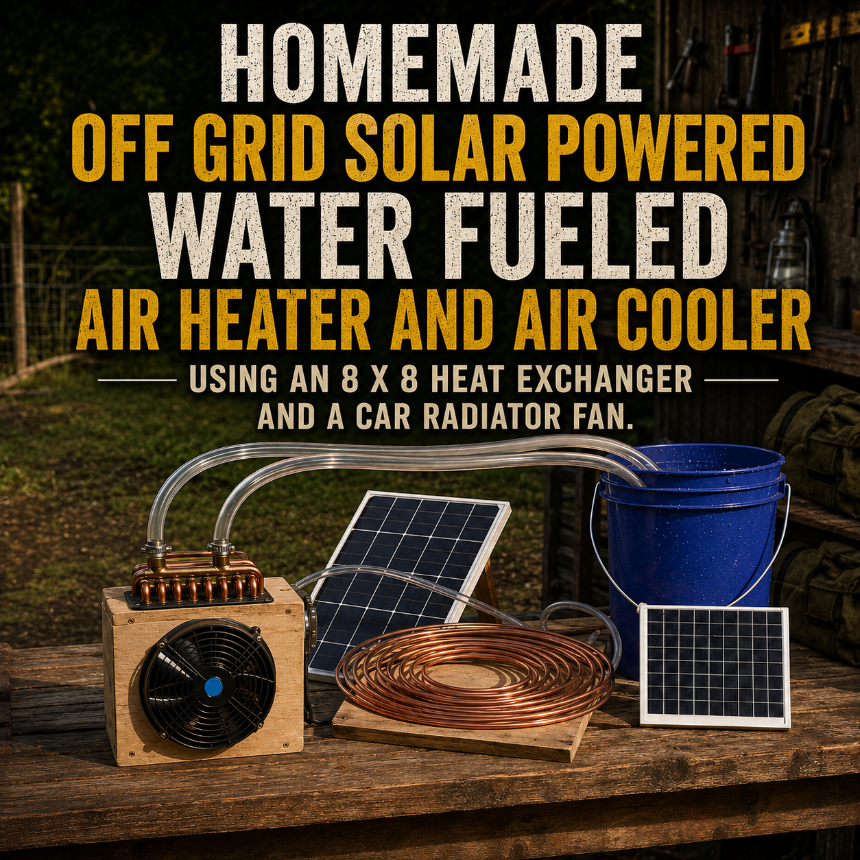
A compact fan, a small water-to-air heat exchanger, and a circulation pump can become a useful off-grid temperature-control experiment.
Fill the reservoir with hot water, and the fan blows warmer air into the room.
Fill it with ice water, and the fan blows cooler air while moisture condenses on the cold coil.
The system resembles a small hydronic fan-coil unit. Larger buildings commonly circulate hot or chilled water to air-handling equipment, where fans move room air across coils to provide heating or cooling. (The Department of Energy’s Energy.gov)
A homemade version can be helpful for:
- Temporary spot heating
- Cooling a small work area with stored ice
- Using heat collected by a separate solar-thermal system
- Moving stored heat into a greenhouse or workshop
- Testing small off-grid energy systems
- Recovering heat from an appropriate hot-water source
- Providing limited comfort during a short outage
But it is not a fuel-free furnace or a homemade air conditioner.
The device only moves heat. Something else must first heat or chill the water.
What This System Actually Does
The basic water loop is:
Reservoir → pump → heat exchanger → return hose → reservoir
The air path is:
Room air → guarded fan → heat exchanger → warmer or cooler air
In heating mode, hot water loses heat as it moves through the coil. The fan transfers part of that heat into the surrounding air.
In cooling mode, cold water gains heat. The air becomes cooler as it passes through the coil, while the water in the reservoir gradually warms.
The system stops providing useful heating when the water approaches room temperature.
It stops providing useful cooling for the same reason.
Four Important Corrections to the Original Project
1. Water is not the fuel
Water stores and transports thermal energy, but it does not create that energy.
For heating, the water must first be warmed by something such as:
- A solar-thermal collector
- A properly designed boiler
- A heat pump
- A conventional water heater
- Safely heated water transferred from another container
- Waste heat from suitable equipment
For cooling, the water must be chilled by:
- Ice
- Frozen water bottles
- A chiller
- Cold groundwater in a suitable system
- Nighttime or seasonal thermal storage
Calling the project “water-fueled” hides the most important question:
Where did the heat—or cold—come from?
2. A 100-watt panel cannot run all the listed equipment
The source project lists:
- An 80-watt radiator fan
- A circulation pump
- A 150-watt heating element
- A 100-watt solar panel (Practical Survivalist)
The fan and heating element alone require 230 watts, before adding the pump, controller losses, or startup current.
A 100-watt panel cannot supply a continuous 230-plus-watt load.
The situation is even less favorable in real conditions. Solar-panel nameplate ratings are measured under standardized laboratory conditions: 1,000 watts per square meter of sunlight and a 25°C cell temperature. Actual sunlight is often weaker, while operating panels are usually hotter, so real output commonly falls below the nameplate rating. (The Department of Energy’s Energy.gov)
A 100-watt panel may be able to operate a carefully selected fan and small pump in strong sunlight, but only when their measured combined demand remains below the panel’s available output.
For dependable operation, a small off-grid system generally uses:
- Solar panel
- Charge controller
- Battery
- Fuse protection
- Properly sized wiring
- Fan and pump loads
DOE describes batteries, controllers, and inverters where applicable as normal parts of many off-grid photovoltaic systems. (The Department of Energy’s Energy.gov)
3. A 25,000-BTU coil does not guarantee 25,000 BTU per hour
A heat exchanger may be advertised with a 25,000-BTU-per-hour rating, but that rating applies only under specific test conditions.
Performance depends on:
- Entering water temperature
- Leaving water temperature
- Water flow rate
- Airflow through the coil
- Entering air temperature
- Coil cleanliness
- Fan pressure
- Installation and duct resistance
A high-rated coil connected to a tiny heat source cannot create more heat than the source provides.
A 150-watt electric heater converts to approximately:
150 watts × 3.412 = 512 BTU per hour
Even with perfect heat transfer, it cannot continuously supply 25,000 BTU per hour.
The heat exchanger may be capable of transferring 25,000 BTU per hour when connected to a properly sized boiler and supplied with sufficient hot-water flow. That does not mean a 150-watt element or small solar panel can produce that output.
4. The cooling water requires drainage and humidity control
The source says the system does not add humidity because the water remains inside the loop. That can be true when the loop is closed and dry.
However, when the coil surface becomes colder than the room’s dew point, moisture in the air condenses on the fins.
That means cooling mode needs:
- A condensate tray
- A controlled drain
- Waterproof surfaces beneath the unit
- Regular cleaning
- Protection for the fan and electrical wiring
A cold coil may actually remove some moisture from the air, but only when the condensate is collected and removed. Without a tray, water can drip onto the floor, wood frame, fan motor, wiring, or nearby furniture.
Understanding the Real Thermal Capacity
The amount of useful heating or cooling depends heavily on the reservoir.
One gallon of water weighs approximately 8.34 pounds. Raising or lowering one pound of water by 1°F requires approximately one BTU.
Five-gallon heating example
Five gallons of water weighs roughly 41.7 pounds.
If it enters the system at 140°F and is allowed to cool to 100°F:
41.7 pounds × 40°F = approximately 1,668 BTU
If the room receives heat at an average rate of 3,000 BTU per hour, that stored heat would theoretically last about 33 minutes.
Real performance will be lower because the reservoir, hoses, frame, and surrounding room also absorb heat.
Five-gallon cooling example
If five gallons of chilled water warms from 40°F to 60°F:
41.7 pounds × 20°F = approximately 834 BTU of sensible cooling
That is useful for spot comfort, but not enough to cool an entire house for hours.
Ice adds much more cooling capacity because it absorbs substantial energy while melting. However, the ice had to be produced somewhere, usually by a powered freezer.
The unit relocates stored cooling; it does not generate it.
A Safer Project Design
This version uses:
- A vented, insulated reservoir
- A continuous-duty 12-volt circulation pump
- An 8×8 hydronic heat exchanger
- A fully guarded 12-volt fan
- Separate fused circuits
- A battery-buffered solar supply
- A condensate tray
- Temperature-rated hoses
- No loose immersion heating element
The water loop remains open to atmospheric pressure through the vented reservoir.
This avoids trapping heated water inside a sealed homemade system.
Materials
Heat exchanger
Use one new 8×8-inch water-to-air heat exchanger or heater core that is rated for:
- The intended water temperature
- The intended flow rate
- The selected hose size
- Indoor air use
- The selected working fluid
A new hydronic heat exchanger is preferable to a salvaged automotive heater core.
A used vehicle core may contain:
- Ethylene-glycol antifreeze
- Stop-leak products
- Corrosion
- Oil or dirt
- Weak solder joints
- Residue that produces odors when warmed
If a used core is selected, it should be professionally inspected, cleaned, pressure-tested, and dedicated to a nonpotable closed loop.
Fan
Choose one:
- Guarded 12-volt axial fan
- Enclosed 12-volt blower
- Automotive radiator fan fitted with rigid front and rear guards
The fan should have published information for:
- Operating voltage
- Normal current
- Startup current
- Airflow
- Continuous-duty rating
- Direction of rotation
An automotive radiator fan can move substantial air, but it can also draw significant current and cause injury when its blades are exposed.
OSHA requires fans located within seven feet of a working surface to have securely mounted guards with openings no larger than one-half inch. While that rule governs workplaces, the same design principle is sensible for a homemade household unit. (OSHA)
Circulation pump
Use a 12-volt pump specifically rated for:
- Continuous operation
- The loop’s maximum temperature
- The selected fluid
- Required flow
- Required vertical lift or head pressure
A small brushless hydronic circulation pump is generally a better choice than a random aquarium or bilge pump.
Do not use an aquarium pump with hot water unless its manufacturer explicitly permits that temperature.
Do not use a submersible pump outside water or a dry-mounted pump underwater.
Reservoir
Use a five- to ten-gallon insulated container with:
- Secure lid
- Small open vent
- Temperature rating
- Stable base
- Pump connection
- Return connection
- Drain fitting
- Accessible thermometer
The lid should reduce evaporation and prevent spills, but the reservoir must not become a sealed pressure vessel.
Possible choices include:
- Insulated beverage cooler
- Heavy-duty water container
- Purpose-built hydronic buffer tank
- Sturdy lidded bucket placed inside an insulated enclosure
Do not use a thin storage tote for hot water.
Tubing and fittings
Use hose rated for:
- Continuous hot-water exposure
- Cold-water exposure
- Pump suction
- The chosen fittings
- Indoor use
Suitable options may include manufacturer-rated:
- EPDM heater hose
- Reinforced silicone hose
- Hydronic hose
- PEX tubing with compatible fittings
Ordinary thin vinyl tubing may soften, collapse, leak, or detach when heated.
Include:
- Hose barbs
- Stainless-steel clamps
- Drain valve
- High-point bleed fitting
- Shutoff valves for maintenance
- Spare clamps
- Pipe insulation
Do not install valves in a way that can trap heated water in a completely sealed section.
Frame and air shroud
- ½-inch plywood or sheet metal
- Two side rails
- Exterior or cabinet screws
- Weatherstripping
- Aluminum foil HVAC tape
- Fan guards
- Carrying handles
- Rubber feet
- Removable service panel
Use foil HVAC tape rather than ordinary cloth duct tape near the coil.
Condensate equipment
- Shallow metal or plastic drain pan
- Drain fitting
- Clear drain hose
- Covered collection container
- Washable filter screen, optional
The pan should extend beneath the entire coil.
Electrical system
- Solar panel sized for the measured load
- Solar charge controller
- 12-volt battery
- Main battery fuse
- Separate fan fuse
- Separate pump fuse
- DC switch
- Fan-speed controller
- Correctly sized stranded copper wire
- Insulated terminals
- Protective wiring loom
- Battery enclosure
- Voltmeter, optional
The fan-speed controller must be rated above both the fan’s normal current and startup surge.
Monitoring
- Water thermometer
- Air thermometer
- Optional infrared thermometer
- Battery voltmeter
- Flow indicator, optional
- Leak detector or water alarm, optional
Recommended Basic Layout
The safest flow order is:
Reservoir outlet → pump → lower heat-exchanger port → upper heat-exchanger port → reservoir return
Feeding the lower port and returning from the upper port helps move trapped air upward and out of the coil.
The reservoir should remain:
- Below the heat exchanger when practical
- Stable
- Accessible
- Protected from tipping
- Far enough from the electrical components that a spill cannot reach them
Place the pump close to the reservoir.
Many small circulation pumps perform best when their inlet is already filled with water rather than being expected to draw water through a long dry hose.
Step 1: Test the Fan and Pump Separately
Before building the frame, test each component according to its instructions.
Fan test
Connect the fan temporarily through:
- Proper fuse
- Switch
- Suitable 12-volt source
Confirm:
- Correct rotation
- Airflow direction
- Normal current
- Excessive vibration
- Bearing noise
- Startup behavior
Disconnect power before touching the blades.
Do not test an unguarded fan where clothing, hair, fingers, children, or pets can reach it.
Pump test
Place the pump in the arrangement specified by its manufacturer.
Circulate cool water through a short temporary loop.
Check:
- Flow direction
- Noise
- Leaks
- Current draw
- Ability to restart
- Temperature rise
- Required priming
Do not conduct the first pump test with hot water.
Record the measured fan and pump current. These values will determine the wiring, fuse, controller, battery, and panel requirements.
Step 2: Build the Fan and Coil Frame
Cut a plywood or sheet-metal panel large enough to support the fan and heat exchanger.
A compact frame may use:
- Back panel approximately 12×14 inches
- Two 2×2 or 1×3 side rails
- Coil mounted on the intake side
- Fan mounted on the discharge side
- Guard on both exposed faces
The exact dimensions depend on the selected components.
Cut the fan opening slightly smaller than the fan’s mounting flange.
Fasten the fan using bolts, washers, and locking nuts where possible.
Do not rely on zip ties or tape as the primary attachment.
Install rubber washers or vibration isolators when the fan causes the wooden frame to resonate.
Step 3: Create a Proper Air Shroud
Air follows the easiest path.
Without a shroud, part of the fan’s output may flow around the coil rather than through it.
Build a sealed air channel between the fan and heat exchanger.
Use:
- Plywood strips
- Sheet metal
- Weatherstripping
- Foil HVAC tape
- Removable screws
Seal gaps along:
- Coil perimeter
- Fan frame
- Side rails
- Corners
- Service panels
Do not tape directly across the heat-exchanger fins.
All moving air should pass through the coil face.
Step 4: Install the Fan Guards
Fit a rigid guard over both accessible sides of the fan.
The guard must:
- Remain fixed during operation
- Resist being pushed into the blades
- Contain loose objects
- Allow sufficient airflow
- Have no sharp edges
- Be removable only with deliberate action
Do not operate the unit while a guard is removed.
Do not insert fingers or tools through the guard to stop a rotating blade.
Wait until it stops fully after power is disconnected.
Step 5: Install the Condensate Pan
Cooling mode can create significant condensation.
Place a pan beneath the entire lower edge of the coil.
The pan should:
- Extend beyond both sides
- Have raised edges
- Slope toward its outlet
- Be removable for cleaning
- Avoid contact with the fan motor
- Drain through a secure hose
Route the drain to:
- A covered bucket
- Floor drain where appropriate
- Safe outdoor drainage point
Do not drain water across a walking path.
Do not allow the hose end to sit in stagnant water, which can encourage odors and backflow.
CDC recommends keeping water-containing equipment, cooling coils, and condensate pans clean and free of biofilm, corrosion, dirt, and debris. It also recommends avoiding long periods of stagnant water. (CDC)
Step 6: Mount the Heat Exchanger
Attach the heat exchanger to the frame using its mounting tabs or purpose-made brackets.
Do not:
- Drive screws into the coil
- Crush the fins
- Bend the inlet tubes
- Support the unit only by its hose fittings
- Allow the copper or aluminum tubes to rub against sharp wood
Leave space to inspect and tighten the hose connections.
Install the water ports so the system can drain after use.
Step 7: Prepare the Reservoir
Install the following fittings:
- Low outlet to the pump
- Upper return connection
- Drain valve
- Thermometer
- Small vent
The return hose should discharge beneath the lid but should not splash aggressively.
A submerged return reduces noise and evaporation, but it must not create a sealed siphon that makes maintenance difficult.
Strap the reservoir to a stable base when the unit may be moved.
Never carry the frame and a full reservoir as one assembly.
Five gallons of water adds more than 40 pounds.
Step 8: Connect the Water Loop
Connect the loop in this order:
- Reservoir outlet
- Pump inlet
- Pump outlet
- Lower heat-exchanger port
- Upper heat-exchanger port
- Reservoir return
Slide hose completely over each barb.
Install clamps behind the barb’s raised ridge.
Tighten the clamps enough to prevent leaks without cutting into the hose.
Support the hoses so their weight does not pull on the coil fittings.
Avoid:
- Kinks
- Sharp bends
- Low loops that cannot drain
- Contact with fan blades
- Contact with sharp metal
- Routing near battery terminals
Insulate hot-water hoses to reduce heat loss and protect users from contact burns.
Step 9: Wire the Low-Voltage System
A safer solar arrangement is:
Solar panel → charge controller → fused battery → fused fan and pump circuits
Do not connect the fan, pump, battery, and panel randomly.
Use the wiring diagram supplied with the charge controller and components.
Install the main battery fuse close to the positive battery terminal.
Use separate protected circuits for:
- Fan
- Pump
- Controls
The current can be estimated with:
Amps = watts ÷ volts
An 80-watt fan at 12 volts may draw approximately 6.7 amps during normal operation. Startup current may be higher.
Measure the actual draw rather than relying only on labels.
Keep:
- Connections above the water reservoir
- Terminals covered
- Wires secured
- The battery in a protective enclosure
- Positive and negative conductors clearly identified
- Wiring away from the condensate tray
Low voltage reduces shock risk, but a battery can still deliver enough current to overheat wiring or start a fire during a short circuit.
Step 10: Size the Solar Supply Realistically
Add the measured continuous power of:
- Fan
- Pump
- Controller losses
- Any gauges or accessories
Suppose the fan uses 80 watts and the pump uses 18 watts.
The continuous load is approximately:
80 + 18 = 98 watts
A single 100-watt panel is not a reliable choice for that 98-watt load because the panel reaches its rating only under standardized conditions, while real output varies with sunlight, temperature, orientation, clouds, wiring, and controller losses. (The Department of Energy’s Energy.gov)
A more realistic system might use:
- 150- to 200-watt panel
- Correctly sized controller
- 12-volt battery
- Low-voltage disconnect
- Fan-speed control
The exact size should be based on measured current and desired operating time.
A lower-power fan may offer better overall performance than an 80-watt automotive fan, especially when the system will run from a small panel.
Step 11: Cold Leak-Test the System
Fill the reservoir with cool water.
Leave the fan and pump unpowered initially.
Inspect every fitting.
Then start the pump while the fan remains off.
Let the water circulate for at least 30 minutes.
Check:
- Hose clamps
- Pump housing
- Coil fittings
- Reservoir connections
- Drain valve
- Return fitting
- Condensate tray
- Electrical separation
Place dry paper beneath each connection. Even a slow leak becomes visible quickly.
Repair every leak before heating or chilling the reservoir.
Step 12: Purge Air From the Loop
Air trapped inside the heat exchanger reduces water flow and heat transfer.
With cool water:
- Open the high-point bleed fitting.
- Run the pump at low speed.
- Allow air to escape.
- Close the fitting when water flows steadily.
- Recheck the reservoir level.
- Repeat if the pump becomes noisy.
Never open a bleed fitting while the system contains dangerously hot water.
Do not run the pump dry.
Operating in Heating Mode
Use a safe external hot-water source
The safest beginner method is to fill the reservoir with water heated by a separate, controlled appliance.
Possible sources include:
- Conventional water heater
- Purpose-built solar-thermal system
- Properly installed hydronic heater
- Hot water transferred carefully in a closed container
Do not suspend a loose heating element in a plastic bucket.
CPSC recently warned that certain portable immersion water heaters could ignite within minutes when partly or completely out of water; 235 fires had been reported for those products. (U.S. Consumer Product Safety Commission)
An AC immersion heater placed beside a homemade water loop also introduces shock risk. CPSC recommends GFCI protection where electrical equipment is used near water. (U.S. Consumer Product Safety Commission)
Begin with moderate water temperature
For the first test, begin around 100°F to 110°F.
After confirming:
- No leaks
- Stable hose connections
- Suitable component ratings
- Safe air temperature
You may gradually increase the reservoir temperature within the limits of every component.
For a beginner indoor unit, keeping the water near or below 120°F reduces scald risk. CPSC recommends approximately 120°F for household hot water and warns that 150°F water can cause a severe burn within seconds. (U.S. Consumer Product Safety Commission)
Startup order
- Fill and vent the reservoir.
- Start the pump.
- Confirm water circulation.
- Inspect for leaks.
- Start the fan at low speed.
- Measure inlet and outlet air temperatures.
- Increase fan speed gradually.
Do not begin by running the fan at maximum speed.
A slower fan may produce warmer discharge air, while a faster fan may transfer more total heat but at a lower outlet temperature.
Operating in Cooling Mode
Prepare the reservoir
Add:
- Cool water
- Frozen water bottles
- Sealed ice packs
- Bagged ice where appropriate
Frozen bottles are less messy than loose ice and can be returned to a freezer later.
Do not use dry ice in a sealed water reservoir.
Startup order
- Fill the reservoir.
- Start the pump.
- Confirm circulation.
- Start the fan on low.
- Watch the coil for condensation.
- Check the drain pan.
- Increase fan speed as needed.
The coil may begin dripping within minutes in warm, humid air.
Monitor the reservoir
Record:
- Starting water temperature
- Room temperature
- Discharge-air temperature
- Time
- Condensate amount
When the reservoir approaches room temperature, cooling performance will drop sharply.
Add more ice or stop the system.
Do not expect one bucket of ice water to cool a full house.
Does It Really Provide 1,500 CFM?
That number should be treated cautiously.
A radiator fan may have a high free-air airflow rating when operating without restriction. Installing a heat exchanger directly in front of it creates resistance.
Actual airflow will depend on:
- Coil thickness
- Fin density
- Shroud design
- Fan type
- Voltage
- Fan speed
- Guard design
- Dust accumulation
- Air leakage around the coil
A fan rated at 1,500 CFM in open air may move substantially less air through a dense 8×8 coil.
Use the rating as a component specification, not a promise of installed performance.
Does It Really Heat or Cool 1,000 Square Feet?
Not with a small tub of water and a 100-watt panel.
Floor area alone does not determine heating or cooling demand.
Demand depends on:
- Outdoor temperature
- Insulation
- Air leakage
- Ceiling height
- Window area
- Sun exposure
- Number of occupants
- Appliances
- Humidity
- Desired temperature difference
The unit may noticeably affect a small enclosed area when connected to a sufficiently hot or cold reservoir.
It is more realistic as:
- Spot heater
- Small-room comfort device
- Greenhouse air circulator
- Workshop experiment
- Tent or shelter cooler using ice
- Heat-recovery fan coil
It should not be advertised as a replacement for a furnace, heat pump, or air conditioner.
Where the Heat Can Come From Off Grid
Solar-thermal collector
A water-heating solar collector can warm a separate reservoir much more efficiently than converting sunlight into electricity and then using a resistance element.
The collector must be designed to address:
- Expansion
- Overheating
- Scalding
- Freezing
- Pressure
- Appropriate water-contact materials
Keep a homemade beginner fan-coil loop vented and separate from household plumbing.
Wood or biomass heat
Do not wrap improvised copper tubing around a stove or flue and connect it to a closed loop.
Water trapped near a strong fire can boil, create steam, and build destructive pressure.
A wood-fired hydronic source requires an engineered heat exchanger, expansion capacity, pressure relief, temperature control, and experienced installation.
Waste heat
Heat may be recovered from equipment only when:
- The equipment manufacturer permits it
- Exhaust gases remain completely separated
- No combustion gases can enter the room
- The added equipment does not cause overheating
- The water loop cannot leak into electrical machinery
Do not place a heat exchanger in generator exhaust.
Generators must remain outdoors and far from openings because of carbon-monoxide hazards.
Stored hot water
For temporary use, carrying safely heated water to the insulated reservoir is the simplest arrangement.
It is limited, but it is easy to understand and measure.
Electrical Safety Near Water
Keep all electrical equipment:
- Above the reservoir
- Away from the condensate pan
- Protected from splashes
- Strain-relieved
- Properly fused
- Enclosed where practical
Use waterproof connectors only where they are truly required and rated for the application.
Do not operate equipment with:
- Cracked wiring
- Loose terminals
- Corroded connectors
- Wet controller
- Swollen battery
- Overheating wire
- Repeatedly blown fuse
When any AC-powered equipment is used near the water system, use GFCI protection and follow the appliance manufacturer’s requirements. CPSC identifies GFCIs as an important protection against electrocution where electricity and water may come together. (U.S. Consumer Product Safety Commission)
Never reach into the water while an AC heater, pump, or appliance is connected.
Water Hygiene and Stagnation
This loop should be treated as nonpotable.
Do not drink from it, cook with it, or use it for washing wounds.
Water that remains warm and stagnant can support biofilm and bacterial growth. CDC notes that nonsterile water systems and equipment can grow Legionella when temperature, stagnation, sediment, and maintenance conditions are favorable. The temperature range of roughly 77°F to 113°F is particularly favorable for growth. (CDC)
Reduce stagnation by:
- Draining the loop after use
- Flushing before reuse
- Cleaning the reservoir
- Removing sediment
- Drying the coil where practical
- Avoiding long dead-end hoses
- Keeping the condensate tray clean
- Never intentionally spraying loop water into the air
A properly sealed coil should not aerosolize the circulating water. Stop operation immediately if a leak allows the fan to spray droplets.
Common Building Mistakes
Calling water the fuel
The reservoir only stores heat or cold supplied by another source.
Using a 100-watt panel for a 230-plus-watt load
The fan and heating element already exceed the panel rating before the pump is counted.
Separate the water-heating source from the fan-and-pump electrical system.
Using a loose immersion element
A poorly controlled element can cause fire, shock, melted plastic, scalding water, or dry-fire damage.
Use an appropriate external hot-water source.
Using an unguarded automotive fan
The blades can cause serious cuts.
Install rigid guards on both accessible sides.
Using ordinary PVC hose for hot water
Some plastic tubing softens at elevated temperatures.
Use hose with a documented continuous-temperature rating.
Sealing the reservoir
Heated water expands.
Keep the beginner system vented rather than turning it into an improvised pressure vessel.
Forgetting the condensate pan
Cold coils create water.
Install the tray before the first cooling test.
Allowing air to bypass the coil
A poor shroud reduces useful heat transfer.
Seal the fan-to-coil frame carefully.
Depending on the coil’s advertised BTU rating
Actual output cannot exceed the energy being supplied by the hot or cold water.
Leaving the system unattended
A loose hose, failed clamp, stopped pump, blocked fan, or overheated wire can create damage quickly.
Storing the loop full
Stagnant water encourages odor, corrosion, slime, and biological growth.
Drain and clean it.
Using automotive antifreeze indoors
Automotive coolant can be toxic and creates a serious problem if the coil or hose leaks.
For freezing conditions, drain the system completely or use a professionally specified hydronic fluid in a suitable closed loop.
Optional Improvements
Use a lower-power blower
A purpose-built 12-volt blower may provide better pressure through the coil while consuming less energy than an oversized radiator fan.
Compare airflow through the installed coil—not just free-air ratings.
Add a washable air filter
A thin filter on the intake side keeps dust from clogging the coil.
Do not use a filter so restrictive that it overheats or overloads the fan.
Add thermostatic control
A low-voltage thermostat can switch the fan or pump when the room reaches a set temperature.
The controller must be rated for the actual current or operate an appropriate relay.
Add a low-water shutoff
A float switch can stop the pump if the reservoir level falls too low.
Add temperature sensors
Measure:
- Reservoir water
- Coil outlet water
- Intake air
- Discharge air
These readings reveal whether changes to water flow or fan speed improve performance.
Add quick-disconnect fittings
Use leak-resistant fittings rated for the water temperature.
Quick disconnects simplify cleaning and storage.
Add a larger insulated reservoir
A larger reservoir extends operating time but becomes much heavier.
Ten gallons of water weighs more than 83 pounds.
Keep the reservoir on the floor rather than on the fan frame.
Add separate heating and cooling reservoirs
Two containers prevent warm water, meltwater, and residue from being repeatedly mixed.
Label them clearly.
Maintenance
Before every use
- Inspect hoses.
- Check clamps.
- Examine the fan guards.
- Test the drain.
- Check the wiring.
- Confirm the battery fuse.
- Turn the fan by hand while disconnected.
- Inspect the reservoir.
After heating mode
- Allow the pump to circulate until temperatures fall.
- Turn off the fan.
- Disconnect electrical power.
- Drain the loop.
- Wipe the reservoir.
- Inspect for softened hose.
After cooling mode
- Empty the condensate tray.
- Wash and dry the tray.
- Drain the coil.
- Clean the reservoir.
- Dry the frame.
- Inspect for mold.
- Remove wet insulation.
Seasonally
- Clean dust from coil fins.
- Straighten minor fin damage with an appropriate fin comb.
- Check the pump impeller.
- Inspect wire terminals.
- Test the charge controller.
- Inspect battery condition.
- Replace brittle hose.
- Tighten structural fasteners.
Do not use high-pressure water to clean the coil while it remains attached to the fan and electrical equipment.
Is This Project Worth Building?
Yes—when it is described accurately.
A small water-to-air fan coil is valuable for:
- Learning hydronic heat transfer
- Testing a solar-electric system
- Using stored ice more effectively
- Moving heat from a separate hot-water source
- Providing temporary spot comfort
- Building practical off-grid skills
Its limitations are substantial:
- Water does not create energy.
- A small reservoir changes temperature quickly.
- A 100-watt panel cannot operate the listed fan, pump, and heater simultaneously.
- Coil ratings do not equal actual system output.
- Cooling creates condensation.
- Heating creates scalding and leak risks.
- The fan requires guarding.
- The water loop requires cleaning.
- It cannot replace whole-house HVAC.
The most practical version uses solar electricity only for the fan and circulation pump.
Heating or chilling the water remains a separate process.
Build the unit before an emergency.
Test it first with cool water.
Measure every electrical load.
Record how quickly the reservoir changes temperature.
The results will tell you whether the device is useful for your room, climate, and available energy supply.
Final Safety Note
This project is a temporary, low-voltage water-to-air heat-transfer unit—not a furnace, air conditioner, pressure vessel, or primary home-heating system.
Keep the loop vented. Use a fully guarded fan, temperature-rated hoses, fused wiring, and a pump approved for continuous operation at the intended water temperature.
Do not place a loose AC immersion heater in the reservoir. Keep electrical connections above and away from water, and use GFCI protection whenever AC equipment is present.
Treat hot water as a scalding hazard. Collect and drain condensation during cooling mode. Keep the reservoir and coil clean, avoid stagnation, and never use the loop water for drinking.
Do not connect a homemade coil to a wood stove, pressurized boiler, household water system, generator exhaust, or combustion appliance without professional design and required safety controls.