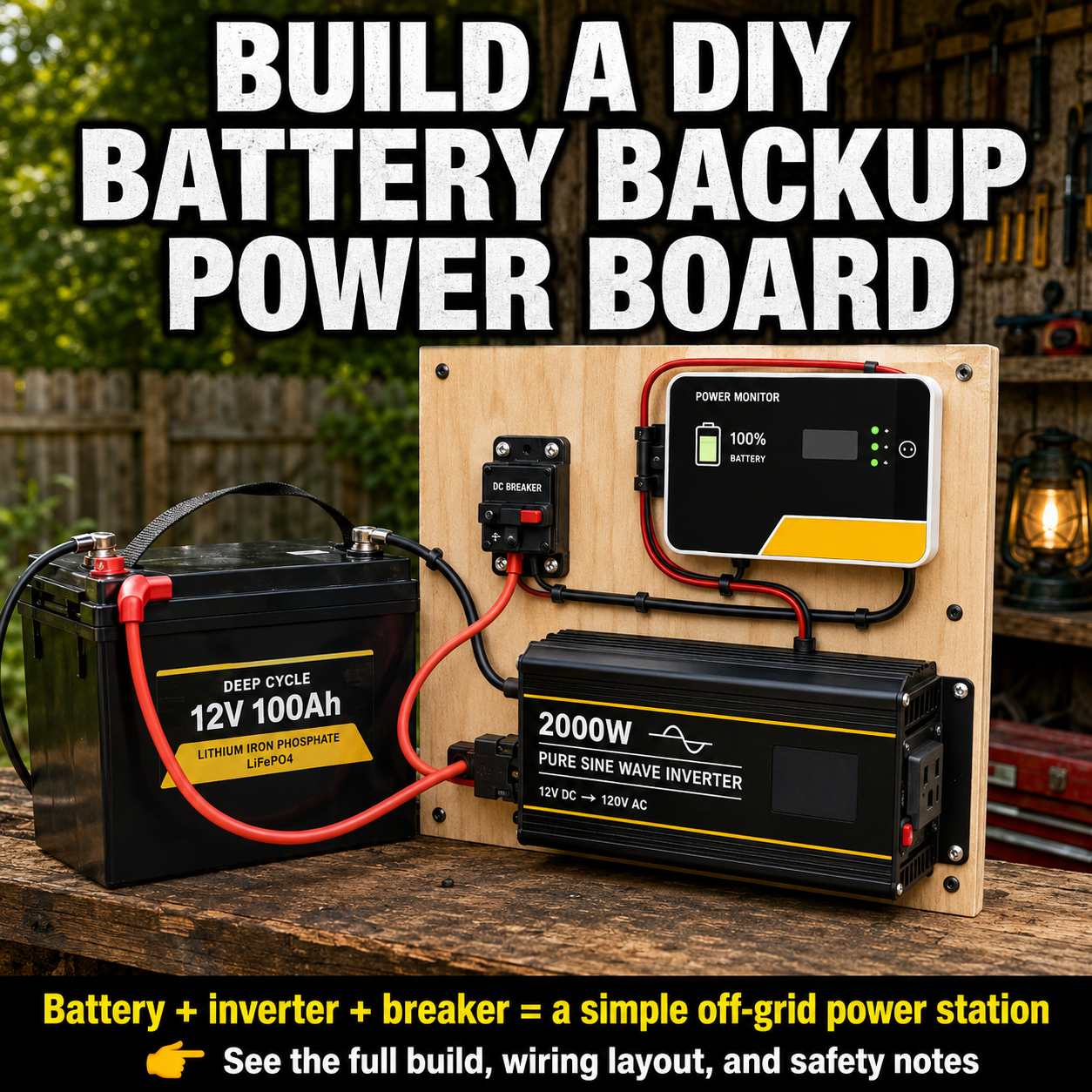
A power outage does not always require a large generator.
For keeping phones charged, running lights, powering a fan, operating a laptop, or supporting a few small appliances, a properly designed battery-and-solar system can provide quiet backup electricity without gasoline, fumes, or engine maintenance.
This project uses a LiFePO4 battery, an MPPT solar charge controller, a pure sine wave inverter, and a set of protected DC outlets. The components can be mounted on a portable board, installed in a ventilated cabinet, or incorporated into a small emergency-power cart.
The goal is not to power an entire house. It is to create a focused backup system for essential devices.
Important Safety Notice
A 12-volt battery can deliver enough current to overheat wires, melt insulation, damage equipment, or start a fire. Every positive cable connected to the battery must have properly selected circuit protection.
Cable size, fuse ratings, breaker ratings, grounding, battery settings, and connection procedures must follow the manuals supplied with the exact equipment you purchase.
Do not connect this power station to a household wall outlet. Feeding electricity into home wiring through an outlet can create an electrocution and fire hazard. Permanent home integration requires an approved transfer system installed according to applicable electrical codes.
Anyone who is not comfortable crimping large cables, calculating DC current, or verifying polarity should have the final wiring inspected by a qualified electrician or experienced solar installer.
What This Power Station Can Do
A system built around one 12.8-volt, 100Ah LiFePO4 battery stores approximately 1,280 watt-hours of energy before accounting for conversion losses.
That makes it useful for devices such as:
- LED lamps
- Phones and tablets
- Internet routers
- Rechargeable radios
- Laptop computers
- Small fans
- Camera batteries
- CPAP equipment, after confirming compatibility and runtime
- Some efficient 12-volt refrigerators
- Small power tools used intermittently
It is generally not a practical system for electric heaters, kettles, hot plates, large air conditioners, electric dryers, or other high-wattage heating appliances.
Those loads can drain a small battery bank extremely quickly and may exceed the battery’s discharge limit.
Start With the Battery—not the Inverter
One of the most common DIY mistakes is selecting a large inverter without checking whether the battery can supply it.
Many standard 12V 100Ah LiFePO4 batteries use a 100A battery-management system. A battery with that rating may be limited to approximately 1,280 watts of continuous DC output. After inverter losses, the practical continuous AC output will be lower.
Installing a 2,000-watt inverter does not automatically mean the battery can deliver 2,000 watts.
For a single battery with a 100A continuous-discharge limit, a pure sine wave inverter in the 600-to-1,000-watt range is usually a more balanced choice. A larger inverter requires a battery or battery bank with a sufficiently high continuous-discharge rating, together with appropriately sized cables, busbars, fuses, and disconnects.
Always check:
- The battery’s continuous-discharge rating.
- The inverter’s maximum continuous DC input current.
- The inverter’s surge requirement.
- The battery BMS surge limit.
- The required cable and fuse specifications.
Suggested Components
The exact parts should be selected as one compatible system rather than purchased separately based only on wattage.
Core equipment
- One 12.8V 100Ah LiFePO4 deep-cycle battery with an internal BMS
- Pure sine wave inverter matched to the battery’s discharge capability
- MPPT solar charge controller with a LiFePO4 charging profile
- Approximately 200 to 400 watts of solar panels
- Positive and negative DC busbars
- Fused DC distribution panel
- USB and 12V accessory outlets
- Main battery disconnect
- Battery monitor with a shunt, if desired
- PV disconnect or properly rated solar breaker
Electrical protection
- Main battery fuse
- Separate inverter fuse
- Separate charge-controller fuse
- Fuse for the DC accessory panel
- Properly rated fuse holders or DC breakers
- Protective covers for positive terminals
Wiring supplies
- Manufacturer-specified battery and inverter cables
- Solar cable rated for outdoor PV use
- Tinned copper lugs of the correct size
- Adhesive-lined heat-shrink tubing
- Cable clamps and strain relief
- Cable labels
- Large-cable crimper
- Multimeter
- Insulated hand tools
Do not choose one cable size for the entire project. The inverter, charge controller, solar array, and accessory panel may all require different wire sizes.
Circuit protection should be selected to protect the wire while also meeting the equipment manufacturer’s specifications. A fuse should never be rated higher than the connected wire can safely carry.
Step 1: Calculate Your Essential Loads
Before mounting anything, list the devices you expect to use.
Write down each device’s running wattage and how many hours it may operate per day.
Use this basic formula:
Daily energy use = watts × hours of operation
For example:
- Four 8-watt LED lights used for five hours: 160Wh
- A 50-watt fan used for eight hours: 400Wh
- A 60-watt laptop used for three hours: 180Wh
- Phone and radio charging: approximately 60Wh
The total would be about 800Wh.
That is within the general energy range of a 1,280Wh battery after allowing for inverter losses, battery reserve, temperature, cable loss, and variations in appliance consumption.
For AC appliances, a conservative runtime estimate can be calculated with:
Usable battery watt-hours ÷ appliance wattage = approximate runtime
Actual performance will vary. Refrigerators, pumps, compressors, and power tools may have startup surges that are several times higher than their normal running consumption.
Step 2: Choose a Safe Mounting Arrangement
Lay the components out before drilling any holes.
Keep the inverter close enough to the battery to minimize the length of the high-current DC cables. Longer cable runs create more resistance and voltage drop.
Provide open space around:
- Inverter cooling fans
- Charge-controller heat sinks
- Battery terminals
- Fuse holders
- Disconnect switches
- Busbars
Mount exposed electrical connections behind protective covers. Avoid placing tools, loose hardware, or metal objects where they could fall across the battery terminals.
A metal or other noncombustible mounting panel is preferable. When wood is used, mount heat-producing equipment with appropriate standoffs and follow the clearance requirements in each product manual.
Do not seal the inverter and charge controller inside an airtight container. Both components may require airflow to prevent overheating.
Step 3: Build the Main DC Distribution System
A clean installation normally uses positive and negative busbars rather than stacking numerous cables directly on the battery terminals.
A simplified arrangement looks like this:
Battery positive → main fuse → battery disconnect → positive busbar
Battery negative → battery-monitor shunt, when used → negative busbar
Each major component then receives its own connection:
- Positive busbar → inverter fuse → inverter
- Positive busbar → controller fuse → charge controller
- Positive busbar → accessory-panel fuse → DC fuse block
- All corresponding negative cables → negative busbar
Large loads such as inverters should have dedicated circuit protection rather than sharing a small breaker with the charge controller or USB panel. Battery-side faults can produce extremely high current, which is why protection is installed between the battery and connected equipment.
Place the main battery fuse as close to the positive battery terminal as the fuse manufacturer and applicable electrical rules require.
Keep all disconnects switched off while assembling the system.
Step 4: Connect the Inverter
The inverter converts the battery’s DC electricity into household-style AC electricity.
Use a pure sine wave model for sensitive electronics, chargers, medical equipment, audio devices, and appliances with electronic controls.
Connect the inverter directly to its protected busbar circuit using the cable size specified by the inverter manufacturer.
A 2,000-watt inverter operating from a 12-volt system can draw well over 150 amps at high output. Current rises further when voltage drops or conversion losses are considered. Current manufacturer guidance may call for approximately a 250A fuse and very heavy battery cable for a 12V 2,000W inverter, but the exact requirements depend on the model and installation.
This is why ordinary automotive accessory wire or general-purpose 8-gauge cable should not be assumed suitable for a large inverter.
Keep the inverter switched off until all connections have been checked.
Step 5: Install the MPPT Charge Controller
The MPPT controller regulates electricity coming from the solar panels and applies the correct charging profile to the battery.
Confirm that:
- The controller supports LiFePO4 batteries.
- Its maximum PV voltage is higher than the solar array’s maximum possible open-circuit voltage.
- Its output-current rating is appropriate for the array.
- Its battery-charging settings match the battery manufacturer’s requirements.
- Temperature compensation is disabled or configured appropriately for lithium chemistry when required by the manufacturer.
Connect the controller’s battery output to the busbars through its own fuse or breaker.
Do not connect the solar panels yet.
Many MPPT manufacturers instruct installers to connect the battery side first so the controller can recognize the system voltage. Victron, for example, specifies connecting the battery, allowing the controller to detect system voltage, and then connecting the PV input.
Follow the procedure supplied with your specific controller.
Step 6: Add the DC Accessory Panel
A fused DC panel allows small 12V devices to operate without using the inverter.
This is more efficient because the battery’s electricity does not have to be converted from DC to AC.
The panel may include:
- USB-A charging ports
- USB-C Power Delivery ports
- 12V automotive-style sockets
- Anderson-style connectors
- A digital voltmeter
- Individual branch fuses
Connect the panel to the positive busbar through a fuse sized for the panel wiring. Connect its negative lead to the negative busbar.
Each accessory circuit should have protection appropriate for its wire and outlet rating.
Do not rely on a small dashboard voltmeter as your only measure of battery capacity. LiFePO4 voltage remains relatively steady through much of its discharge cycle. A shunt-based battery monitor provides a more useful estimate of energy entering and leaving the battery.
Step 7: Connect the Solar Panels
Before making the PV connection, verify:
- Solar-panel polarity
- Array open-circuit voltage
- Controller voltage limit
- Connector condition
- Cable rating
- PV disconnect position
- Controller battery settings
Cover the solar panels or keep the PV disconnect open while working on the connectors.
Connect the solar array to the controller’s PV input only after the controller has been properly connected to the battery side, unless the controller’s manual explicitly gives a different procedure.
Once connected, uncover the panels or close the PV disconnect. Confirm that the controller displays incoming solar power and battery-charging current.
A 200-watt panel will not normally produce its full label rating throughout the day. Weather, panel temperature, shade, sun angle, cable loss, and controller efficiency all affect output.
Recharging a nearly empty 1,280Wh battery from a 200-watt array may require more than one day when only a limited number of peak-sun hours are available.
Step 8: Test the System Gradually
Do not begin testing with a hair dryer, electric heater, or other high-wattage appliance.
Start with the system disconnected from solar input.
- Confirm that every fuse and cable is correctly installed.
- Check positive and negative polarity with a multimeter.
- Inspect each lug for movement or exposed copper.
- Confirm that no tools remain near the battery.
- Close the main disconnect.
- Verify battery voltage at the busbars.
- Switch on the charge controller.
- Test the USB and 12V outlets.
- Switch on the inverter without an AC load.
- Plug in a small lamp or other low-wattage device.
- Increase the test load gradually while monitoring voltage, current, and temperature.
Stop immediately if a cable, connection, fuse holder, or breaker becomes hot.
After the first moderate-load test, switch everything off and inspect the system again. Loose connections create resistance and can generate dangerous heat.
Realistic Runtime Examples
Assuming approximately 1,000Wh of practical AC energy after maintaining a reserve and accounting for conversion losses, estimated runtimes could look like this:
- 10W LED light: roughly 80 to 100 hours
- 40W fan: roughly 20 to 25 hours
- 60W laptop: roughly 14 to 16 hours
- 100W television: roughly 8 to 10 hours
- 500W appliance: roughly 1.5 to 2 hours
These figures are estimates, not guarantees.
An appliance may cycle on and off, draw additional startup current, operate at different power levels, or consume standby power. Battery temperature and condition also affect usable capacity.
Common Mistakes to Avoid
Buying an oversized inverter
A large inverter does not create more energy. It may encourage users to connect loads the battery and wiring cannot safely support.
Using one breaker for several major components
The inverter, controller, and accessory panel should normally have separately protected circuits.
Installing undersized cables
High-current 12V systems require much heavier conductors than many beginners expect. Cable size must account for current, distance, insulation temperature rating, voltage drop, installation environment, and fuse size.
Ignoring the battery BMS limit
The inverter’s wattage must be compatible with the battery’s continuous and surge-current ratings.
Connecting solar first
Some controllers may fail to detect battery voltage correctly or may be damaged when the manufacturer’s required connection order is ignored.
Mounting components in an enclosed box
Inverters and charge controllers can produce heat. Blocked ventilation may cause shutdowns, reduced performance, or equipment damage.
Backfeeding a wall outlet
Never use a male-to-male cord or attempt to energize household wiring from the inverter. Use extension cords directly from the power station, or have an approved transfer system professionally installed.
Ways to Expand the System Later
A well-planned system can grow as your needs change.
Possible upgrades include:
- Additional solar-panel capacity
- A larger MPPT controller
- A second compatible battery in parallel
- Higher-current busbars
- A larger battery monitor
- More DC charging ports
- A wheeled enclosure
- Shore-power or generator charging through an approved LiFePO4 charger
- A higher-voltage 24V system for larger loads
Before adding batteries in parallel, confirm that the manufacturer permits it. Batteries should generally be compatible in model, chemistry, voltage, capacity, state of charge, and condition.
Do not simply install a larger inverter without reassessing the battery bank, BMS limits, cables, fuses, disconnects, busbars, ventilation, and grounding.
Final Thoughts
A DIY solar power station can be a valuable addition to an emergency plan, but reliability comes from careful sizing—not from choosing the largest inverter or the cheapest components.
For many households, one 100Ah LiFePO4 battery paired with a modest pure sine wave inverter and 200 to 400 watts of solar is enough to keep communication devices, lighting, fans, and small electronics working during a temporary outage.
Build around the devices you genuinely need. Protect every circuit. Follow the manufacturers’ wiring diagrams. Test the system before an emergency.
A smaller, correctly designed power station is far more useful than an oversized system with unsafe wiring and unrealistic expectations.